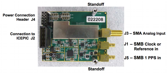
ICE-A2D-M14
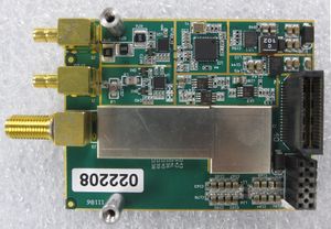
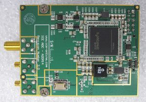
The ICE A2D-M14 is a 14-bit A/D module for use with the ICE-PIC5, ICE-PIC6, ICE-PIC7, and ICE-PIC8 series of high-speed interface cards. (The latter is recommended.)
Software selection allows for the use of an onboard clock synthesizer or direct clock input at a user desired sample rate. The onboard clock synthesizer uses a 10MHz reference from either an external source (J2) or via an onboard oscillator (TCXO).
The A2D-M14 module incorporates a variable gain input stage, which allows for real-time gain settings of -11dB to +20dB in 1dB steps and is user-software controlled. Additionally, the variable gain stage can be used to mute or to disable completely analog input to the A/D.
The use of external 10 MHz and 1 PPS reference signals allows for precision time stamping of digitized data with better than 2.5 nanosecond accuracy, independent of sample rate.
Contents
Features
- 14-bit resolution
- 250 MSamp/sec (300 MSamp/sec on select units - call)
- AC-coupled input
- Analog input nominal 0 dBm
- Maximum input +10 dBm (at minimum gain)
- SFDR of 30 MHz tone at max sample rate is > 84 dB
- 3dB sample and hold bandwidth 40 KHz - 405 MHz
- External 1PPS input for precision time stamp of data
- Single-site module for use with ICE-PIC series cards and ICEPOD subsystems
Applications
- Multichannel, multimode receivers
- Base station infrastructure
- AMPS, IS-136, CDMA, GSM, WCDMA
- Single-channel digital receivers
- Antenna array processing
- Communications instrumentation
- Radar, infrared imaging
- Instrumentation
Specifications
Input Specifications
| Parameter | Minimum | Typical | Maximum | Units |
|---|---|---|---|---|
| Analog Input | 0 dBm | +5 dBm |
dBm | |
| Analog 3dB Passband | 0.04 |
405 |
MHz | |
| External Clock Input1 (AC-coupled) | 0.5 |
1.0 |
2.0 |
V p-p |
| External Ref1 (AC-coupled) |
0.5 |
1.0 |
2.0 |
V p-p |
| Analog Input Impedance | 50 | Ohms | ||
| Sample Clock | 402 | 250 | MHz |
Notes:
- Operation using external reference of 10MHz replaces the external clock input. Sample clock is then generated from the 10MHz reference.
- Sample rates below 40 MSPS require decimation flag in module configuration.
Absolute Maximum Ratings
| Parameter | Value |
|---|---|
| Electrical | |
| AVcc |
5.0 VDC |
| DVcc | 3.3 VDC |
| PPS Input | 0 to 6 Vpeak into 50ohm |
| External Clock Input | 0 to 6 Vpeak into 50ohm |
| Analog Input Power | 10 dBm (50ohm ref) |
| Environmental | |
| Operating Temperature | -10 to +65 °C |
| Storage Temperature | -40 to +85 °C |
WARNING: Operation of this module beyond any of these parameters may cause permanent damage. Exposure to absolute maximum ratings for extended periods may affect module reliability. Operation of the module beyond these specified parameters voids the factory warranty.
Example Plots
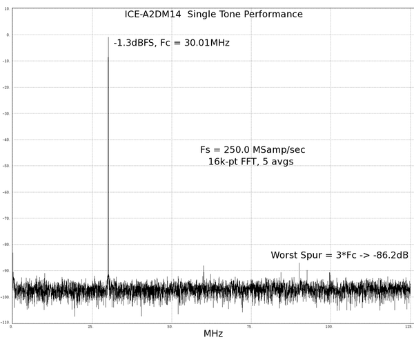
Single-Tone Performance of ICE-A2D-M14
- Sample Rate (MHz): 250
- Bits/Sample: 14
- Typical SFDR: >84dB
- ENOB: 13.7
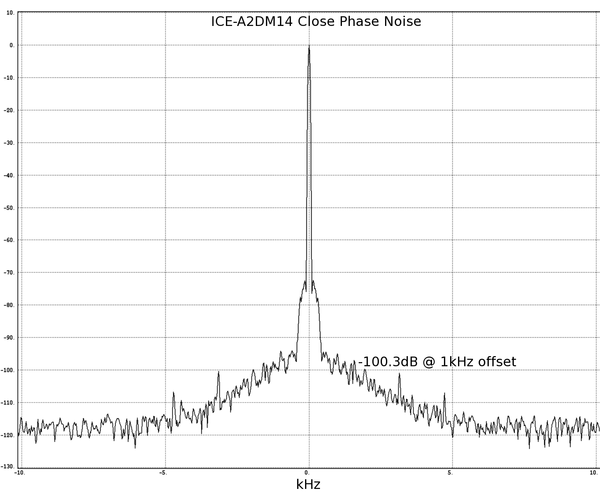
Close in Phase Noise Performance of ICE-A2D-M14
Connectors
| Connector | Manufacturer | Part Number | Description | J-Number |
|---|---|---|---|---|
| 1 Pulse Per Second (PPS) In | Emerson | 131-1701-371 | Rt. Angle SMB Connector | J5 |
| Power Connection | Standard 2-pin Header | J4 | ||
| Standoff (2 each) |
Physical Connection | |||
| Data (J2) | Samtec | QSE-020-01-F-D-A | 40-Pin Connector |
ICE Interface Cables
| ICE-CAB-SB5 (for J1, J5) | 5 ft. BNC to SMB cable |
| ICE-CAB-SMA (for J3) | 5 ft. BNC to SMA cable |
Connectors Diagram
Status
This model is in production. For pricing, please see the Pricing page.
