ICE-GPS
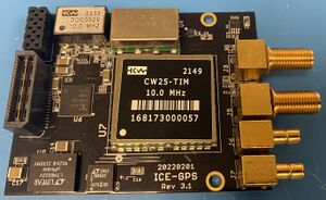
The ICE-GPS is a GPS-driven, mixed-signal phase-lock loop, providing a 1 PPS output, an IRIG-B output, and generating a 10MHz sine output from an extremely low jitter voltage-controlled crystal oscillator (VCXO). The 10MHz output is disciplined from an onboard GPS receiver, which drives the long-term frequency stability. The onboard GPS receiver at the core of the ICE-GPS is the Conner Winfield CW25 timing receiver.
The board is formatted as an ICE I/O module for use with the ICE-PIC8, ICE-POD, ICE-PAC, or ICE-TRAY. The antenna input is available on an SMA connector and will operate an active antenna at 5V. The 10MHz is available on an SMA connector, while 1PPS and IRIG-B are available on SMB connectors, each able to drive four 50 ohm loads.
The ICE-GPS communicates to the host computer through the base ICE card using C-callable library functions. These calls allow access to all NMEA/TSIP protocol information made available by the CW25 module. The user can observe the status of the unit, time of day, position, and current satellite quality/configuration information via either of the two protocols.
Contents
Features
- Stratum 1 time source
- G.811-compliant
- Phase-locked 10MHZ output
- Low 10MHz phase noise (-76db@10Hz, -100dB@100Hz, -126dB@250Hz)
- Precision 1PPS output locked to 10MHz
- Commercial temperature (0-70C)
- SMA connector for GPS antenna input and 10MHZ clock output
- SMB connectors for 1PPS and IRIG-B outputs
- Single-site module for use with ICE-PIC8 series cards and ICE-TRAY systems
Applications
- Precision time and frequency reference
Specifications
Input/Output Specifications
| Parameter |
Minimum | Typical | Maximum |
Units |
|---|---|---|---|---|
| Analog Input |
dBm | |||
| Analog Input Impedance |
50 |
Ohms | ||
| 10MHz Clock Output |
.5 |
1.0 |
1.0 |
V p-p |
| 1PPS Output |
0 |
1.0 |
3.3 |
V |
| IRIG-B Output |
0 |
1.0 |
3.3 |
V |
| Output Impedance |
12.5 |
50 |
Ohms |
Notes:
- Outputs buffered to drive 1-4 50 ohm loads
Absolute Maximum Ratings
| Parameter |
Value | Units | Conditions |
|---|---|---|---|
| Electrical | |||
| AVcc |
5.0 |
VDC |
|
| DVcc | 3.3 |
VDC |
|
| Analog Input Power | +10 |
dBm (50ohm ref) |
|
| Clock Output | 0 to 5 | Vpeak into 50ohm |
|
| PPS Output |
0 to 5 |
Vpeak into 50ohm |
|
| IRIG-B Output |
0 to 5 |
Vpeak into 50ohm |
|
| Environmental | |||
| Operating Temperature | -10 to +65 | Degrees C | |
| Storage Temperature | -40 to +85 | Degrees C | |
WARNING: Operation of this module beyond any of these parameters (temperature, voltage, and input power) may cause permanent damage. Exposure to absolute maximum ratings for extended periods may affect module reliability. Operation of the module beyond these specified parameters voids the factory warranty.
Connectors
| Connector |
Manufacturer | Part Number | Description | J-Number |
|---|---|---|---|---|
| Power Connection |
3M |
929852-01-05-RA | Standard 10-pin Header | J2 |
| Standoff (2 each) |
Physical Connection |
ICE Interface Cables
| ICE-CAB-SMB5 (for J6, J7) | 5 ft. BNC to SMB cable |
| ICE-CAB-SMA5 (for J3, J5) | 5 ft. BNC to SMA cable |
Connectors Diagram
Note the connectors on the image below from top to bottom: GPS antenna in, CLK out, PPS out, IRIG-B out:
Status
This model is in production. For pricing, please see the Pricing page.


