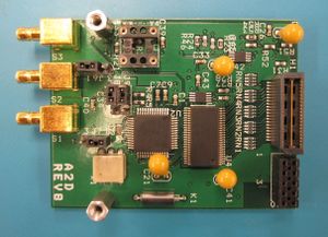
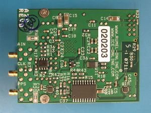
ICE-A2D-r8
From ICE Enterprises
Analog to Digital Converter Module
Contents
Features
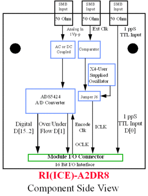
- Utilizes TI ADS5424
- 14-bit 105 MSamp/sec A/D converter 1Vp-p analog input range
- Jumper-selectable AC- or DC-coupled analog input
- External clock derived via a comparator, AC-coupled 1Vp-p
- Oscillator socket (for user supplied clock, jumper selectable with external comparator clock)
- External connector for 1-PPS LVTTL input-stored in bit 0 of 16 bit word (14-bit data MSB-aligned)
- Over/underflow output on data bit 1 of 16-bit word (14-bit data MSB-aligned)
Note: For Use Only With ICE-PIC5XL or ICE-PIC6 or ICEPIC8(Consult Factory)
Jumper Settings
DC- or AC-Coupled
| Jumper | DC-Coupled1,2 | AC-Coupled |
|---|---|---|
| J7 | 1 & 2 SHORT | 2 & 3 SHORT |
| J8 | 1 & 2 SHORT | 2 & 3 SHORT |
| J9 | 1 & 2 SHORT | 2 & 3 SHORT |
Notes:
- For sampling rates Of 2 MSPS and below, DC-coupling should be used.
- DC-coupled is the default setting when delivered.
Digital 3.3V Power Source
| Jumper | Voltage Regulator1 | Board Header2 |
|---|---|---|
| J3 | 1 & 2 SHORT | OPEN |
| J4 | 1 & 2 SHORT | 2 & 3 SHORT |
Notes:
- 3.3V digital power via voltage regulator (default power setting when delivered)
- 3.3V digital power via board header (not an available source for the ICE-PIC3T or ICE-MBT3)
Analog 5V Power Source
| Jumper | Board Header1 | External2 |
|---|---|---|
| J2 | 2 & 3 SHORT | 1 & 2 SHORT |
Notes:
- 5V analog power via board header (default power setting when delivered)
- 5V power is shared between digital logic and analog logic.
- 5V analog power via external power source:
- For normal operation, you will not need external power connections. Users who wish to supply the analog circuitry a "quieter" external power source, separate from the digital power connection as provided above, can connect to one or both pins of J2 a separate 5V supply.
Addendum:
- For connecting to J2, Digi-Key supplies a terminal housing (Part Number: WM2601-ND).
- You will also need 2 terminals for the housing (Part Number: WM2200-ND).
- Wires: 22-30 AWG.
External Clock Selection
| Jumper | SMB Comparator1 | User Supplied Oscillator2 |
|---|---|---|
| J6 | 1 & 2 SHORT | 2 & 3 SHORT |
Notes:
- Default selection when delivered.
- User supplied oscillator—Oscillator (X4) should be 5V with CMOS output.
Status
This model is in production. For pricing, please see the Pricing page.


