Uncategorized files
Jump to navigation
Jump to search
Showing below up to 195 results in range #1 to #195.
View (previous 250 | next 250) (20 | 50 | 100 | 250 | 500)
 2T3U-08-ssd8.jpg 1,000 × 278; 202 KB
 50t2U-front-300x56.png 280 × 52; 24 KB
 A2D-r8-bottom.jpg 1,221 × 915; 215 KB
 A2D-r8-top.jpg 1,212 × 876; 204 KB
 A2DM14 bottom.jpeg 1,922 × 1,344; 387 KB
 A2DM14 top rotated.jpeg 1,918 × 1,330; 1.47 MB
 A2DR13-connections.png 472 × 337; 172 KB
 A2DR13-diagram.png 538 × 710; 50 KB
 A2DR13-plot-example.jpg 600 × 419; 19 KB
 A2DR13-side-view.jpg 600 × 450; 29 KB
 A2d-r11-chipside.jpg 1,376 × 980; 524 KB
 A2d-r11-top.jpg 1,341 × 959; 396 KB
 A2dm14 nb 30MHz.png 1,365 × 1,119; 79 KB
 A2dm14 wb 30MHz.png 1,365 × 1,119; 97 KB
 A2dr11topview.gif 805 × 812; 24 KB
 A2dr8topview.gif 547 × 722; 20 KB
 Arrow return down right.png 48 × 48; 638 bytes
 Bfcs storm case open.jpg 1,000 × 840; 598 KB
 Briefcase-wide-angle-retouch 884x1074.jpg 869 × 1,056; 225 KB
 Cable and HIC Card web final 1200x1029.jpg 1,200 × 1,029; 702 KB
 D2A-r9-bottom.jpg 1,260 × 952; 181 KB
 D2A-r9-top.jpg 1,350 × 976; 222 KB
 D2AWG-r2-chipside 1000x750.jpg 1,000 × 750; 725 KB
 D2LV-r5-bottom.jpg 1,158 × 888; 129 KB
 D2LV-r5-top.jpg 1,322 × 948; 178 KB
 D2awg data sheet1 140mhz example.gif 649 × 358; 13 KB
 D2awg data sheet1 70mhz example.gif 649 × 358; 12 KB
 D2lvtopview.gif 467 × 608; 9 KB
 D2rf-block-diagram.png 295 × 392; 31 KB
 D2rf-bottom.png 352 × 276; 252 KB
 D2rf-connectors.png 760 × 329; 172 KB
 D2rf-top-vertical.png 333 × 482; 297 KB
 D2rf-top.png 450 × 330; 280 KB
 DR2D-r5-bottom.jpg 1,200 × 1,600; 595 KB
 DR2D-r5-top.jpg 1,200 × 1,600; 561 KB
 DTDMspecs.png 406 × 576; 154 KB
 Deep side computer-side ICEPOD6 grid.jpg 1,130 × 768; 65 KB
 Deep side vertex-side ICEPOD6 grid.jpg 1,130 × 768; 61 KB
 Dip-sw-config1-1010-293x209 mod.png 293 × 209; 36 KB
 Dip-sw-config2-0110-293x210.png 293 × 210; 35 KB
 Dip-sw-config3-1000-293x209.png 293 × 209; 36 KB
 Dipswitches.gif 268 × 194; 22 KB
 E2D-r5-bottom.jpg 1,304 × 964; 230 KB
 E2D-r5-top.jpg 1,600 × 1,200; 618 KB
 E2D.gif 500 × 375; 29 KB
 Email-ltblue-on-while-icon 146x16.png 146 × 16; 5 KB
 Email-ltblue-on-while-icon 158x16.png 158 × 16; 5 KB
 EthernetFrameAlt.png 1,506 × 868; 26 KB
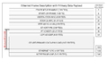 EthernetFramePrimary.png 1,528 × 860; 27 KB
 FAQA2Dr7.gif 646 × 500; 57 KB
 FLZRXD-r1-bottom.jpg 1,170 × 1,042; 522 KB
 FLZRXD-r1-top.jpg 1,260 × 1,142; 261 KB
 FULLPIC5XL.gif 487 × 237; 29 KB
 Fig1-dell-r720-thermal.jpg 2,976 × 2,349; 3.72 MB
 Flzrxdr1topview.gif 844 × 853; 33 KB
 Fpga developers conference.pdf ; 2.43 MB
 GIGEXD-r2-mech-drawing.png 1,200 × 927; 107 KB
 GPSr3 Back.jpeg 1,375 × 845; 217 KB
 GPSr3 Front.jpeg 1,372 × 843; 300 KB
 GigEXD-r2-length-ruler 1200x900.jpg 1,200 × 900; 278 KB
 GigEXD-r2-side 1200x900.jpg 1,200 × 900; 275 KB
 GigEXD-r2-top-a 1200x900.jpg 1,200 × 900; 279 KB
 GigEXD-r2-top-b 1200x900.jpg 1,200 × 900; 247 KB
 GigEXD-r2-width-ruler 1200x900.JPG 1,200 × 900; 287 KB
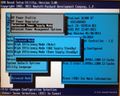
 Hp-dl380-g7-bios-fig1.jpg 1,200 × 951; 897 KB
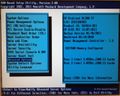
 Hp-dl380-g7-bios-fig2.jpg 1,200 × 956; 781 KB
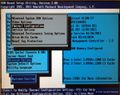
 Hp-dl380-g7-bios-fig3.jpg 1,200 × 961; 778 KB
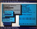
 Hp-dl380-g7-bios-fig4.jpg 1,200 × 948; 804 KB
 Hp-dl380-g7-bios-fig5.jpg 1,200 × 955; 800 KB
 Hp-gen9-first-riser-top.png 1,280 × 889; 1.66 MB
 Hp-gen9-left-riser.png 1,280 × 402; 643 KB
 Hp-gen9-rear-2xpic7.png 1,000 × 191; 313 KB
 Hp-gen9-right-riser.png 1,280 × 409; 756 KB
 Hp-gen9-second-riser-top.png 1,280 × 883; 1.65 MB
 Hsr-block-diagram 369x188.png 369 × 188; 39 KB
 Hsr-example-plots-140MHz 531x293.png 531 × 293; 38 KB
 Hsr-example-plots-70MHz 535x295.png 535 × 295; 37 KB
 Hsr-fig1 470x205.png 470 × 205; 155 KB
 Hsr-fig2 173x118.png 174 × 118; 33 KB
- ICE-2017-Company-Overview.pdf ; 661 KB
 ICE-8T3U-10-SATAII-front 1000x272.jpg 1,000 × 272; 69 KB
 ICE-A2D-m14-connectors-diagram 670x293-rev2.png 670 × 293; 215 KB
 ICE-A2D-m18-performance-diagram 523x502.png 523 × 502; 74 KB
- ICE-BLOCK-Brochure-20171014.pdf ; 463 KB
 ICE-Briefcase-Gen7-Interface2 1000x245.jpg 1,000 × 245; 68 KB
 ICE-Briefcase-Interface3 1000x241.jpg 1,000 × 241; 73 KB
- ICE-COOLER-Brochure-20171014.pdf ; 451 KB
- ICE-D2AWG-M3-Brochure-20171014.pdf ; 519 KB
 ICE-D2AWG-r2-connectors diagram 670x295.png 670 × 295; 227 KB
 ICE-D2AWG-r2 functional block diagram 540x291.png 540 × 291; 64 KB
 ICE-Extension Chassis front web final 1200x107.jpg 1,200 × 107; 87 KB
 ICE-Extension chassis rear web final 1200x122.jpg 1,200 × 122; 158 KB
 ICE-GPS-r1.2-bottom.jpg 1,344 × 959; 429 KB
 ICE-GPS-r1.2-top.jpg 1,444 × 1,033; 455 KB
 ICE-IDP2-DATA-PACK-with-rulers 800x569.jpg 800 × 569; 86 KB
 ICE-IDP2-DATA-Pack-top-front 800x656.jpg 800 × 656; 120 KB
 ICE-LB2D-r2-connectors-diagram 670x269.png 670 × 269; 150 KB
 ICE-PIC6L.jpg 800 × 377; 89 KB
 ICE-PIC6S.jpg 600 × 448; 102 KB
 ICEPOD6-interface-side-with-cover 723x1232.jpg 723 × 1,232; 196 KB
 ICEPOD6-interface-side 723x1239.jpg 723 × 1,239; 250 KB
 ICEPOD6-side-ruler.jpg 800 × 305; 45 KB
 ICEPOD65-interface-bottom-view-extended-shroud 1200x776.png 1,200 × 776; 1.16 MB
 ICEPOD65-interface-side-extended-shroud 1200x409.png 1,200 × 409; 727 KB
 ICEPOD65-interface-side-in-enclosure 932x469.png 932 × 469; 473 KB
- ICEPOD65 doc version 18JUL12 ver16.pdf ; 3.41 MB
 ICEPOD6 and ds sideview 600x438.jpg 600 × 438; 47 KB
- ICEPOD6 doc version 5a.pdf ; 3.57 MB
 ICEVRTPacketDef.png 1,466 × 1,162; 58 KB
 IORemoval.gif 500 × 667; 57 KB
 Ice-a2d-m20-top-cln.png 1,089 × 830; 1.14 MB
 Ice-a2d-m20-top.png 1,089 × 830; 1.08 MB
 Ice-cooler-w-card-side.png 3,800 × 1,721; 961 KB
 Ice-d2awg-m3-bottom.png 797 × 1,137; 987 KB
 Ice-k8m-extract.png 471 × 310; 194 KB
 Ice-pac-face-plate.png 1,119 × 309; 416 KB
 Ice-pac-top.png 1,060 × 872; 896 KB
 Ice-pic7l 1839x783.png 1,839 × 783; 1.62 MB
 Ice-pic8l-extract-labeled 1143x393.png 1,143 × 393; 514 KB
 Ice-sonet-r6-chip-side.jpg 1,000 × 810; 591 KB
 Ice-superpac-a.png 958 × 154; 271 KB
 Ice-superpac-b.png 958 × 147; 234 KB
 Ice-udp-10g-r2-connector-side.jpg 1,000 × 837; 654 KB
 Ice-upac-iface-side.png 454 × 118; 106 KB
 Ice-upac-pwr-side.png 449 × 116; 104 KB
 Iced2e.gif 401 × 416; 5 KB
 Icepod6.5-dock-fans.jpg 800 × 391; 220 KB
 Icepod6.5-dock-side.jpg 1,200 × 360; 287 KB
 Icepod6.5-dock-top.jpg 1,000 × 470; 299 KB
 Icepod6.5-in-dock-with-cover.jpg 1,000 × 541; 402 KB
 Icepod8-a2dm18-tray-interface-side.png 1,125 × 505; 737 KB
 LV2D-r5-bottom.jpg 1,200 × 1,600; 473 KB
 LV2D-r5-top.jpg 1,228 × 902; 161 KB
 Laptopand-icepod.jpg 177 × 166; 6 KB
 Lb2d-m3-bottom.png 375 × 248; 201 KB
 Lb2d-m3-top-vertical-ex.png 742 × 1,143; 1.07 MB
 Lb2d-r2-chipside.jpg 1,203 × 880; 364 KB
 Lb2d-r2-top.jpg 1,179 × 805; 334 KB
 Lb2d data sheet version final side1-resized.jpg 600 × 882; 417 KB
 Logical diagram final.gif 241 × 316; 10 KB
 Lv2dtopview.gif 467 × 608; 9 KB
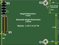 Module2.jpg 643 × 488; 48 KB
 NewPresentation03-13-08.ppt ; 9.7 MB
 PIC5Jumpersettings.gif 225 × 186; 32 KB
- PIC5XLStatus-JV.ppt ; 6.27 MB
 Pdf icon.gif 32 × 32; 1 KB
 Pdf icon 22x22.png 22 × 22; 1 KB
 Pic6 thumb.png 244 × 129; 85 KB
 Pic6jumper.gif 328 × 267; 34 KB
 Pic7-dip-sw-factory 329x266.png 329 × 266; 117 KB
 Ribbon-cable-pinout-crop.jpg 762 × 386; 127 KB
 S6M 160x114.jpg 160 × 114; 15 KB
 S6M chipside 160x111.jpg 160 × 111; 15 KB
 Sma hand tool 400x224.png 400 × 224; 102 KB
 Sma torque wrench 800x178.png 800 × 178; 161 KB
 Sonet-r4-chipside.jpg 1,194 × 1,054; 425 KB
 Sonet-r4-top.jpg 1,009 × 893; 333 KB
 Sonet-r5-chipside.jpg 1,199 × 956; 407 KB
 Sonet-r5-top.jpg 1,299 × 1,055; 521 KB
 Sonetr4topview.gif 699 × 707; 15 KB
 Sonetr5topview.gif 807 × 817; 30 KB
 Storcap320 Published.jpg 3,057 × 1,082; 2.41 MB
 Sync-ch1-chars 989x139.png 989 × 139; 244 KB
 Sync-ch2-chars 990x137.png 990 × 137; 245 KB
 Sync-ch3and4-chars 992x142.png 992 × 142; 241 KB
 Sync-example-diagram 1057x475.png 1,057 × 475; 81 KB
 Sync-front-mount-holes 1033x135.png 1,033 × 135; 131 KB
 Sync-reserve-mount-holes 1031x134.png 1,031 × 134; 136 KB
 Sync1-models.png 934 × 212; 97 KB
 Sync2-ch1-chars.png 2,055 × 291; 1.02 MB
 Sync2-ch2-chars.png 2,055 × 292; 1.02 MB
 Sync2-ch3and4-chars.png 2,056 × 294; 1,012 KB
 Sync2-example-diagram.png 934 × 426; 116 KB
 Sync2-front-angle.png 934 × 142; 145 KB
 Sync2-models.png 934 × 188; 94 KB
 Sync2-rear-angle.png 934 × 118; 195 KB
 Sync2-rear.png 936 × 96; 179 KB
 Sync cold-swap zoom 1200x494.png 1,200 × 494; 532 KB
 Sync front panel 1200x266.png 1,200 × 266; 286 KB
 Sync front panel profiled 800x374.png 800 × 374; 447 KB
 Sync rear panel 1200x149.png 1,200 × 149; 280 KB
 Sync rear panel closeup 800x355.png 800 × 355; 410 KB
 Sync voltageDC 800x341.png 800 × 341; 333 KB
 SynchronICE-Logo 320x120.PNG 360 × 120; 23 KB
 SynchroniICE front leds on 1000x251.png 1,000 × 251; 345 KB
 SynchroniICE rear leds on 1000x551.png 1,000 × 551; 546 KB
 Synchronice-200-rt-corner.png 512 × 268; 174 KB
 UDPr6 virtual diagram.PNG 437 × 564; 23 KB
 UPD-r5-bottom.jpg 1,352 × 812; 205 KB
 UPD-r5-top.jpg 1,364 × 768; 167 KB
 Udpr6 web site side a2.jpg 1,726 × 922; 134 KB
 Udpr6 web site side b2.jpg 2,950 × 1,780; 428 KB
 Udptopview.gif 400 × 591; 8 KB
 V6m 1000x717.jpg 1,000 × 717; 585 KB


