SynchronICE 200 Series
(Redirected from SynchronICE-Gen2)
Four-Channel Distribution of TTL and Analog
The second generation SynchronICE 200 Series is functionally similar to the original SynchronICE, with the addition of a redundant 1+1 power supply and extended ordering options.
Contents
- 1 Features
- 2 Specifications
- 3 Optional Embedded Low Phase Noise Oscillator
- 4 Configurations
- 5 Example Scenarios
- 6 SynchronICE and SunchronICE-200 comparison
- 7 Disclaimers
- 8 Warnings and Cautions
- 9 Status
Features
- 4 channels of distribution:
- Dual 1:8 logic TTL channels
- Dual 1:8 analog channels
- Optional embedded low phase noise oscillator (See Section 3 for more information)
- Forward or reserve rack-mountable
- Redundant 1+1 power supply
Specifications
Front View
Rear View
LED Indicators
Base Model (shown)
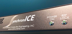
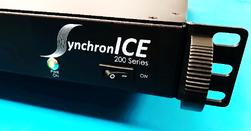
The model ICE-CLKPPS-DST-200 has one Power LED indicator on the front of the chassis. This Power LED will illuminate green as soon as the chassis is turned on with the front power switch.
Models with Embedded Oscillator (not shown)
The model ICE-CLKPPS-DST-293 (and 210) have one Power LED indicator on the front of the chassis and an additional 10MHz reference lock LED on the front and back of the chassis. It typically takes 30-50 seconds for the embedded low-phase-noise reference oscillator to warm up, during which its oven (OCXO) achieves temperature, and it locks to an external 10 MHz reference. Both lock LEDs on the front and back of the chassis will illuminate green when the reference is locked. The warm-up time may be longer depending on ambient temperature at the installed location of the unit.
Channel 1 (CH1), Local Oscillator
Base Model
Note: The reference lock LEDs, J01, and J02 are not populated in this model
| Input impedance | 50 Ω |
| LO Input to Channel 1 (J10) | One Set 1:8 Designated CH1 (J10 series); Recommended 0 to +7 dBm input power |
| Output Level | 1.2 dBm loss relative to input signal level on all 8 outputs J11–J18 with recommended input level Note: If input is exceeded, the unit will accept the input and output +9 dBm on all channels. |
| Input and Output Coupling | AC Coupled |
| Skew between outputs | < +/- 500ps |
| Connectors | SMA Female |
Models with Embedded Oscillator
| LO Reference 10 MHz Input (J02) | +10 dBm Maximum |
| Input impedance | 50 Ω |
| 93 MHz Output (J01) | +9 dBm typical (J01 – J10 Jumpered by default) |
| Output impedance | 50 Ω |
| Input and Output Coupling | AC Coupled |
| LO Input to Channel 1 (J10) | One Set 1:8 Designated CH1 (J10 series); Recommended 0 to +7 dBm input power |
| Output Level | Same as Input Level on all 8 outputs J11–J18. Note: If input is exceeded, the unit will accept the input and output +9 dBm on all channels. |
| Skew between outputs | < +/- 500ps |
| Connectors | SMA Female |
Channel 2 (CH2), 10 MHz Distribution
| 10 MHz Input | -7 - +7 dBm is the expected input for 10 MHz reference distribution. Note: If input is exceeded (> +7 dBm), the unit will accept the input and output +9 dBm on all channels. |
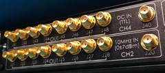
| 10 MHz Output | One Set 1:8 Designated CH2 (J20 series) |
| Output impedance | 50 Ω |
| Output Level | 1.2 dBm loss relative to input signal level on all 8 outputs J21-J28 with expected input level of 0 to +7 dBm |
| Skew between outputs | <+/- 500ps |
| Connectors | SMA Female |
Channel 3 (CH3) and Channel 4 (CH4) DC/TTL
3.3V TTL Output Two Sets 1:8 Designated CH4 (J40 series) and CH3 (J30 series)
| TTL Input | 2.2-5.5VDC |
| Output impedance | 50 Ω |
| Output Logic one: | +3.3 Volts TTL (Threshold +2.0 Volts Minimum) |
| Output Logic zero: | +0.0 Volts TTL (Threshold +0.8 Volts Maximum) |
| Rise Time: | < 1.5 nsec |
| Fall Time: | < 2 nsec |
| Skew between outputs: | <+/- 500ps |
| Connectors: | SMA Female |
| Operating Temperature: | 0°C to 50°C |
| Humidity: | 0 to 95% non-condensing |
| Power Inrush: | 150 Watts momentary |
| Power Consumption: | 30-35 Watts typical |
| Dimensions: | 1.75” Height |
| 16.75” Width (19” Rack Mountable) | |
| 15” Depth (17” including Handles) | |
| Weight | 8 lbs. 12 oz. |
Optional Embedded Low Phase Noise Oscillator
An embedded low phase noise oscillator is included with some models (see Models). The oscillator can be customized for a specific fixed frequency. Please contact ICE for further details.
Example Oscillator Fundamental Specifications
The specifications are based on the 93 MHz Oscillator
| Frequency | 93 MHz | |
| Stability | Output Phase Noise L(f) | (Free-Running) |
| 100 Hz | -120 dBc/Hz | |
| 1 KHz | -150 dBc/Hz | |
| 10 KHz | -170 dBc/Hz | |
| 100 KHz | -171 dBc/Hz | |
| Aging | +/-1 1 x 10e-6 per year after 30 days operating, typical | |
Configurations
Models
The embedded low phase noise oscillator can be customized to a specific fixed frequency. Please contact ICE for more details.
| Model No. | Local Oscillator Frequency |
|---|---|
| ICE-CLKPPS-DST-000 (Base Model) | None |
| ICE-CLKPPS-DST-010 | 10MHz |
| ICE-CLKPPS-DST-093 | 93MHz |
| ICE-CLKPPS-DST-XXX | Please contact for an alternative frequency |
Power Supply
SynchronICE can be shipped with either an AC or DC power supply. The default configuration is an AC Supply. The power supply is cold swappable. The unit powers on immediately when the AC power cord is plugged into the chassis. This is the default configuration for infrastructure units that provide distribution of reference signals to down-stream devices.
AC Power Supply
| AC Input | 100-240 V AC, 5.5-2.5A, 47-63 Hz |
| AC Ouput | +12V, 10 Amps for Each Module |
| AC Wattage | 120 Watts |
DC Power Supply
No longer provided.
Rack Mounting
- SynchronICE can either be front-mounted or reverse-mounted.
- The rack slides are produced by General Devices and are Chassis Trak Telescoping Slides part number C‐300‐S‐124‐RC CC3041‐00‐240.
- Any General Devices C‐300 series rack slides will work with any SyncronICE model.
Forward Mounting
The forward-mounting position is the default orientation when shipped:
Reverse Mounting
To change to reverse mount orientation follow the instructions below:
Example Scenarios
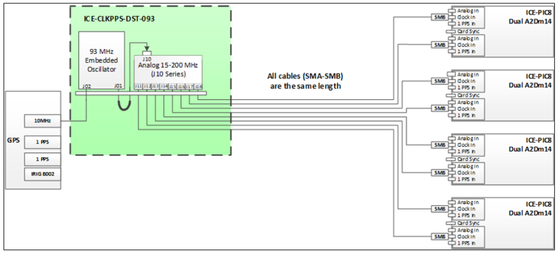
Example Scenario of Channel 1
Embedded LO distribution to 8 ICE-A2Dm14 Modules
Example Scenario of Channel 2
The standard chassis has one 10 MHz input and eight 10 MHz output channels.
Example Scenario of Channels 3, 4
These are both TTL logic channels. 1 PPS and DC IRIGB002 are typical distribution logics.
It is also possible to use the output of the ICE-PIC Card center sync port as an input to one of these channels with the 8 outputs going to down stream ICE-PIC Card center ports (slaves to the card from which the input pulse originates). When using this scenario, the port is no longer used for DC IRIGB, and NNTP time must now be used to determine the second.
SynchronICE and SunchronICE-200 comparison
Previous SynchronICE 100 Series Models
| Model | Description |
|---|---|
| ICE-CLKPPS-DST-000 | 100 Series Base Model |
| ICE-CLKPPS-DST-010 | 100 Series with internal 10MHz Osc |
| ICE-CLKPPS-DST-093 | 100 Series with internal 93MHz Osc |
| ICE-CLKPPS-DST-XXX | 100 Series with custom Osc |
New SynchronICE 200 Series Models
| Model | Description |
|---|---|
| ICE-CLKPPS-DST-200 | 200 Series Base Model with Two 1:8 10 MHz Distribution boards and Two 1:8 TTL Distribution boards (for PPS or IRIG-B) |
| ICE-CLKPPS-DST-210 | 200 Series with internal 10MHz Osc |
| ICE-CLKPPS-DST-230 | 200 Series with 32x 10 MHz, TTL, or IRIG-B SMA Outputs |
| ICE-CLKPPS-DST-293 | 200 Series with internal 93MHz Osc |
| ICE-CLKPPS-DST-2XX | 200 Series with custom Osc |
The main update from the 100 series to the 200 series is the addition or a 1+1 redundant power supply and a power switch. All other functionality has been maintained.
Disclaimers
The ICE-CLKPPS-DST 1U distribution chassis is designed with the specific intent of synchronizing multiple ICE-PIC Cards. It can also provide distribution of TTL signaling and analog sources. Example scenarios are shown above. We recommend testing of this unit to validate your operational scenarios.
All specifications are subject to change without notice. Your application and use scenario for this unit may alter the performance metrics.
Warnings and Cautions
SMA connections J01, J02 are D-Stamped. Do not over-torque. We recommend first to finger tighten with the blue tool provided.
Then we recommended purchasing the SMA Torque Wrench (shown here) to tighten the SMA connectors the remainder of the way down.
4 Inch-Pounds of torque Part # 74 Z-0-0-79 / Ncm 45
45 N-cm = 3.982833 lb-in
74Z-0-0-79 Huber Suhner SMA Torque Wrench, .45Nm, 8mm/.315"
Part #: 419X416 Model #: 74Z-0-0-79
The Huber Suhner 74Z-0-0-79 steel SMA torque wrench is designed for use on SMA connectors. It has a torque of .45 Newton-meters (3.98 inch-pounds) and an opening of 8mm (.315"). Since the proper tightening torque ensures optimal performance over time, this break-over style torque wrench pivots when the torque setting is achieved, preventing over-torque conditions. Ergonomic styling makes the handling of this 4.5" long torque wrench easy.
Status
This model is in production. For pricing, please see the Pricing page.
