ICE-D2AWG-r2
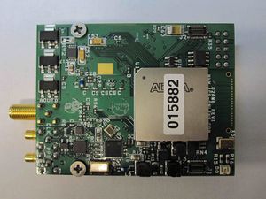
This single-site module has three modes: I/Q modulation, interpolating DAC, and tone generator.
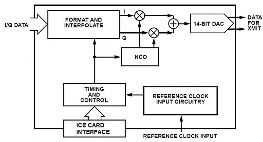
In I/Q modulation mode, up to 125 MSamp/sec of input (16-bit I/Q data) to the digital mixer allows output at any IF frequency up to 500 MHz (Fs/2). The sampling rate is 1 GHz (Fs). A typical usage case would be for playback of complex data for output to a standard IF (70 MHz, 140 MHz). Approximately 118 MHz of useable bandwidth is realized. I/Q data is 16-bits I and 16-bits Q.
In interpolating DAC mode with real data, up to 250 MSamp/sec of 16-bit real samples can be output; the mixer/summer stage is bypassed.
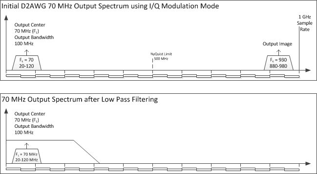
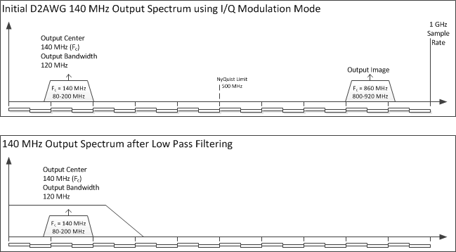
In both modes, a lower digital sample rate can be used. Interpolation from 4 to 256 can be chosen; for example, an input of 12.5 MSamp/sec complex data with the aggregate DAC output rate at 1 GSamp/sec would allow you to center the complex bandwidth at any IF frequency from 0 Hz – 500 MHz. The image is located at Fs-Fc and is easily filtered. A 70 MHz IF with 20 MHz of bandwidth would have an image at 930 MHz.
In tone generator mode, a 1 KHz to 500 MHz, DC-coupled output sine wave can be generated. The 10 MHz reference input is divided by a 32-bit number to produce the sine wave output.
Contents
Features
- Arbitrary waveform generator
- 1 GSamp/sec Interpolating DAC, 14-bit DAC output
- I/Q modulation mode: 16-bit I/Q samples to a digital mixer with complex output on an Intermediate Frequency (IF) from 0 to 500 MHz
- Interpolation from 4 to 256 for lower sample rates and easy image filtering
- Interpolating DAC mode: up to 250 MHz 16-bit real samples
- DC-coupled on output
- Available 31dB range, programmable gain control
- Full scale output: 0 dBm
- External 1PPS input for precision startup triggering
- Single-site module for use with ICE-PIC series cards and ICEPOD subsystems
Applications
- Playback of recorded digital tuner data at IF
- Arbitrary waveform generation
- Tone generation
- Communications transmission
- Instrumentation
- Synthesizer: 1 KHz to 500 MHz
Specifications
Input Specifications - Data
| Digital Input from a File1 | Format | Remarks |
|---|---|---|
| Data Input 16-bits I / Q | 2's Complement | In I/Q modulation mode (complex) up to 125 MSamp/sec |
| Data Input 16-bits I | 2's Complement | In interpolation DAC mode (real) 250 MSamp/sec |
Data – Note 1: The file-based input can come from memory or a disk array: if sourced from memory, the amount of memory in the system must be sufficient to handle the largest file set for a given scenario; if sourced from a disk or disk array, the RAID array must have sufficient I/O speed to sustain the output rate required. Full rate I/Q is 500 MBytes/sec [16 I / 16 Q = 32-bits (4-bytes) equals 125 MSamp/sec].
Input Specifications – External Reference and Triggering
| Parameter | Impedance | Minimum | Typical | Maximum | Units | Remarks |
|---|---|---|---|---|---|---|
| External Ref. – AC-coupled | 50 ohm | +/- 0.5 | +/- 1.0 | +/- 2.0 | V p-p | 10 MHz |
| External Trigger LVTTL | 50 ohm | 0.5 | 2.5 | 4.0 | V p-p | External LVTTL (1PPS may be used)1 |
Triggering – Note 1: The trigger input is inserted on the PPS SMB connection. A LVTTL trigger is expected; a 1PPS input can be used as the trigger. Once a playback output session begins, the 1st rising edge of the inbound 1PPS is read, and the trigger stays high for the remainder of the playback session.
Absolute Maximum Ratings
| Parameter | Value | Units | Conditions |
|---|---|---|---|
| Electrical | |||
| AVcc |
5.0 |
VDC |
|
| DVcc | 3.3 |
VDC |
|
| PPS Input | 0 to 4 |
Vpeak into 50ohm |
|
| External Reference Input | 0 to 4 | Vpeak into 50ohm |
|
| Analog Input Power | +10 |
dBm (50ohm ref) |
|
| Environmental | |||
| Operating Temperature | -10 to +65 | Degrees C | |
| Storage Temperature | -40 to +85 | Degrees C | |
WARNING: Operation of this module beyond any of these parameters may cause permanent damage. Exposure to absolute maximum ratings for extended periods may affect module reliability. Operation of the module beyond these specified parameters voids the factory warranty.
Functional Block Diagram
Example Scenarios
1. Example Scenario with 100 MHz bandwidth centered on 70 MHz
2. Example Scenario with 120 MHz bandwidth centered on 140 MHz
Connectors
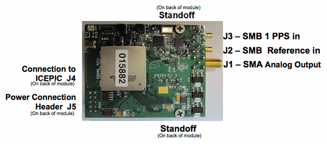
| Connector | Manufacturer | Part Number | Description | J-Number |
|---|---|---|---|---|
| Trigger In | Digi-Key | 131-1701-37 | Rt. Angle SMB Connector | J3 |
| Power Connection | Standard 2-pin Header | J5 | ||
| Standoff (2 each) |
Physical Connection | |||
| Data (J4) | Samtec | QSE-020-01-F-D-A | 40-Pin Connector |
ICE Interface Cables
| ICE-CAB-SB5 (for J2, J3) | 5 ft. BNC to SMB cable |
| ICE-CAB-SMA (for J1) | 5 ft. BNC to SMA cable |
Connectors Diagram
Status
EOL has been declared for this model: see End-of-Life for details. Please call for pricing and availability.
