ICE-A2D-r13
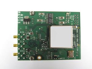
The ICE A2D-r13 is a 12-bit A/D module for use with the ICE-PIC5 or ICE-PIC6 (recommended) series of high-speed interface cards.
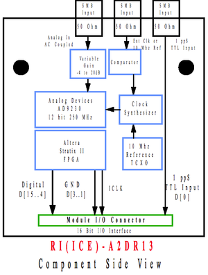
Software selection allows for use of an onboard clock synthesizer or direct clock input at a user desired sample rate. The onboard clock synthesizer uses a 10MHz reference from either an external source (J2) or via an onboard oscillator (TCXO) with sub 1 picosecond jitter performance.
The A2D-r13 module incorporates an input variable gain stage, which allows for gain settings of -4 to +20 dB in 1 dB steps and is user-software controlled.
The use of external 10 MHz and 1 PPS reference signals allows for precision time stamping of digitized data.
Contents
Features
- Uses Analog Devices AD9230 A/D converter
- 12-bit resolution
- Up to 250 MSamp/sec
- 750mV p-p, AC-coupled input
- Ultra low jitter clock synthesizer
- 10 MHz onboard or external reference (software selectable)
- Onboard input gain stage allows for software selection of between -4 and +20 dB of gain
- External 1PPS input for precision time stamp of data
Applications
- Multichannel, multimode receivers
- Base station infrastructure
- AMPS, IS-136, CDMA, GSM, WCDMA
- Single-channel digital receivers
- Antenna array processing
- Communications instrumentation
- Radar, infrared imaging
- Instrumentation
Specifications
Absolute Maximum Ratings
| Parameter | Value | Units | Conditions |
|---|---|---|---|
| Electrical | |||
| AVcc | 0 to 2 | V | |
| DVcc | 0 to 2 | V | |
| PPS Input | 0 to 5 | V | |
| External Clock Input | 0 to 6 | V | |
| Analog Input Power | 0.25 | W | |
| DC Current, Analog Input | 30 | mA | |
| Environmental | |||
| Operating Temperature | -10 to +65 | Degrees C | |
| Storage Temperature | -40 to +85 | Degrees C | |
WARNING: Operation of this module beyond any of these parameters may cause permanent damage. Exposure to absolute maximum ratings for extended periods may affect module reliability. Operation of the module beyond these specified parameters voids the factory warranty.
Miscellaneous
| Parameter | Minimum | Typical | Maximum | Units |
|---|---|---|---|---|
| Analog Input | 0 dBm | +3 dBm | dBm | |
| Analog 3dB Passband | 5 | 270 | MHz | |
| External Clock Input1 (AC-coupled) | 250 | 500 | 1100 | mV p-p |
| External Ref.1 (AC-coupled) | 250 | 500 | 1100 | mV p-p |
| Analog Input Impedance | 50 | Ohms | ||
| Sample Clock | 402 | 250 | MHz |
Notes:
- Operation using external reference of 10MHz replaces the external clock input. Sample clock is then generated from the 10MHz reference.
- Operation below 40 MSamp/sec is possible by over-sampling at 40MHz or above and then decimating the data.
Connector Information
| Connectors | ||||
| Analog In, Clock In, PPS In | Emerson 131-1701-371 | Rt. Angle SMB Connector | S1, S2, S3, | |
| Board Data Connector | Samtec QTE-020-03-F-D-A | 40-Pin Connector | H1 | |
Mating Connectors | ||||
| SMB | Amp # 414946-1, or Huber Suhner # 11SMB-50-2-40 | |||
| Board Data Connector (Mate) | Samtec QSE-020-01-F-D-A | 40-Pin Connector | ||
ICE Interface Cables | ||||
| ICE-CAB-SB5 | 5 ft. BNC to SMB cable | |||
Connection Description
| Connection | Description |
|---|---|
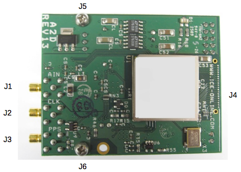
| J1 | Analog Input |
| J2 | Clock Input |
| J3 | PPS Input |
| J4 | Connection to ICE-PIC Card (Connector on back PCB Board) |
| J5 | Retention Screw to standoff (1 of 2) |
| J6 | Retention Screw to standoff (2 of 2) |
Example Plot
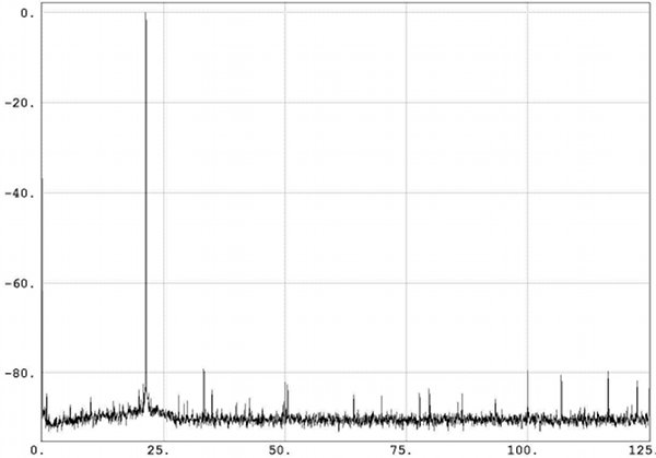
- Single-tone performance
- Sample rate (MHz): 250
- Bits/Sample: 12
- Typical SFDR: >74dB
- ENOB: 12
Status
EOL has been declared for this model: see End-of-Life for details. Please call for pricing and availability.


